Kategorie: Vertical multi-band antenna – 3D printed

  • Vertical multi-band antenna – Cutting Chart

    Vertical multi-band antenna – Cutting Chart

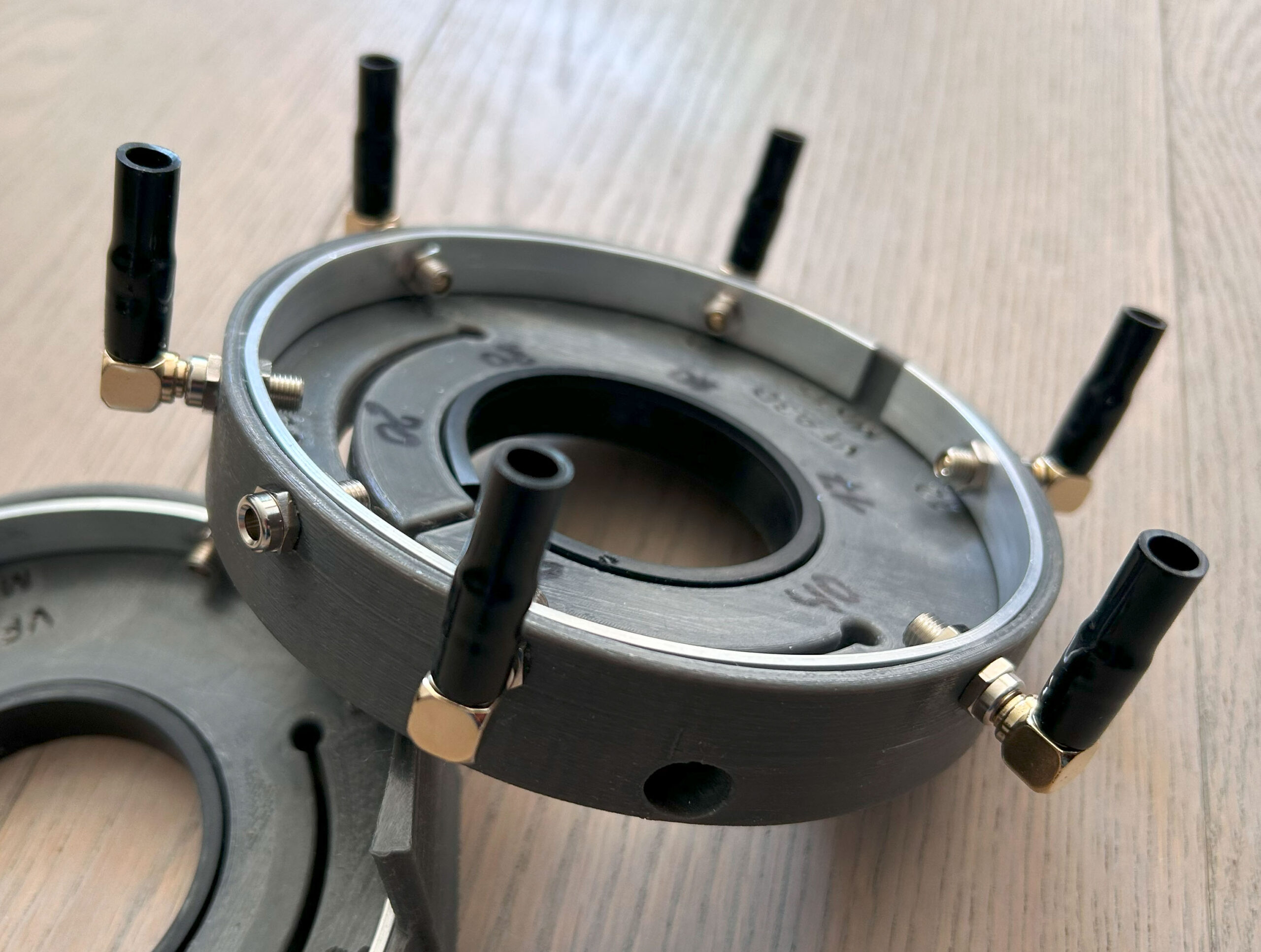
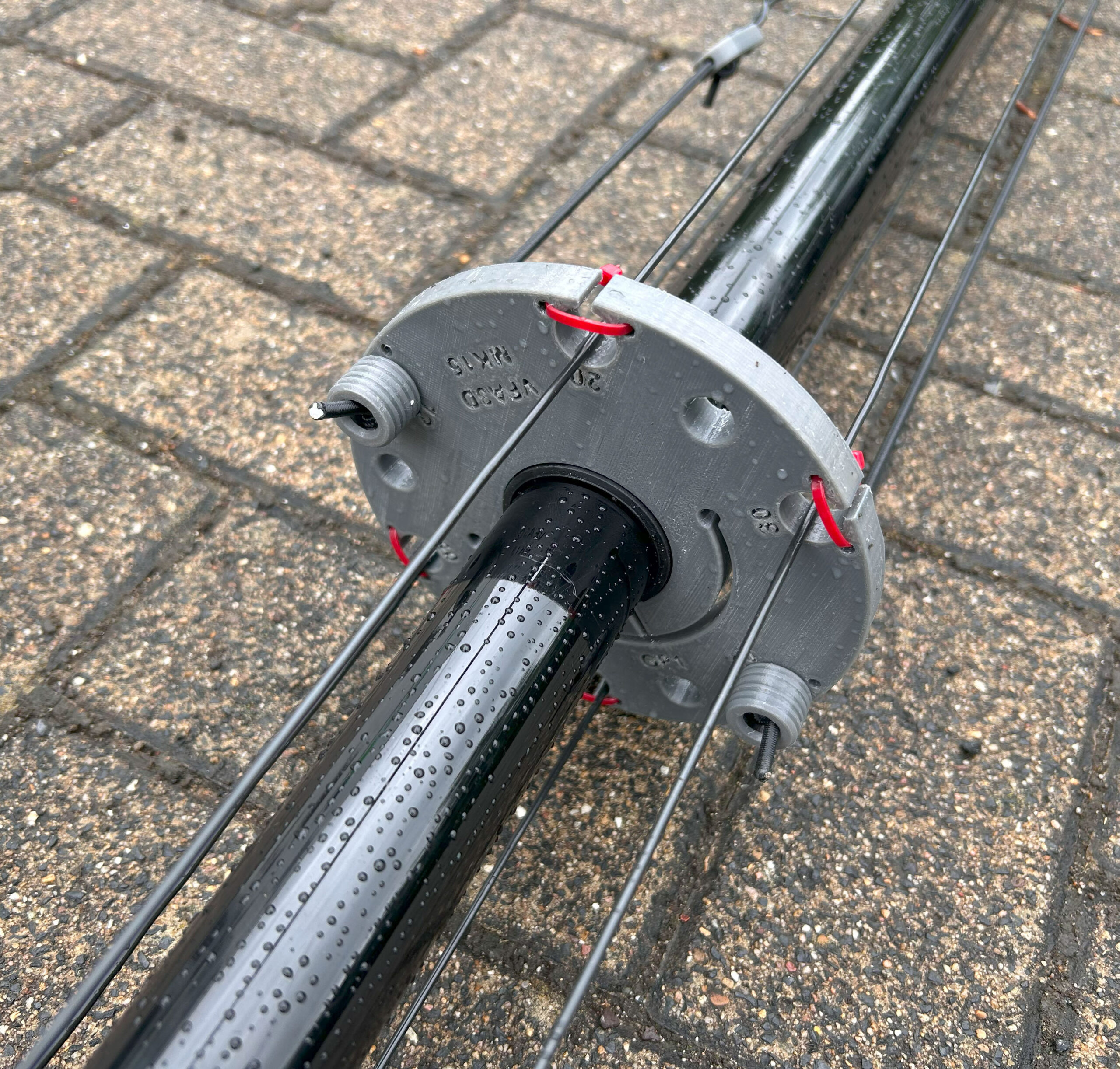
    Cut the active element wire (radiator) to the specified wire length (see Column: Wire length“. Attach the banana plug to one end of the wire. Make a fold back at the other end of the wire (length see column „Foldback Lenght“ and attach the 3d printed „Loop Maker“.

    Cutting chart active elements (radiators):

    BandElement Length (cm) Foldback Length (cm) Wire length (cm)
    10 m23811249
    12 m27317290
    15 msee 40msee 40 msee 40 m
    17 m37414388
    20 m42837465
    30 m67626702
    40 m981501031

    Cutting chart radials:

    Cut a total of 32 wires with a length of 250 cm. Connect 4 wires each with a banana plug. You will then have 8 radial bundles with 4 radial wires each.

    SWR tuning:

    Start SWR tuning with all radiators and radials installed from 40m down to 10m.

    SWR diagram before fine-tuning.

  • Vertical multi-band antenna – threading the radiator elements

    Vertical multi-band antenna – threading the radiator elements

    There are two options for threading the radiator elements. Either via the threading gap. This is a good option if the radiator elements are thickened with shrink tubing at this point. In this case, the radiator element can simply be threaded through the gap. The second option is to close the gap with a cable tie. In this case, the radiator is threaded through the corresponding hole.

  • Vertical multi-band antenna concept

    The VMA3D is based on the M0MCX concept for a vertical multi-band antenna with radiator for the corresponding amateur radio bands. Once tuned, the antenna does not require an antenna tuner and thus enables a quick band change.

    What makes the VMA3D stand out is the integrated clamping device with which the plates and clamping rings hold their position on the pole and the use of rubber C-profiles to distribute the pressure better to the fiberglass pole. There is therefore no need for cable ties or similar to hold the plates in place. I first saw the clamping ring concept on the Ice Cone antenna from DO0PAT.

    The VMA3D also uses 4mm banana sockets and plugs for quick assembly and disassembly. This eliminates the need to screw on eyelets or fork contacts.

    As I don’t have the space to permanently install an antenna, the VMA3D is optimised for portable operation. The aim was to reduce the number of components to a minimum and to use as few special parts as possible. Apart from the 12m spider beam mast, the DX10 antenna wire and some screws, nuts and plugs, everything can be produced using 3D printing.

    I am currently using PETG filament, which offers better temperature and UV resistance than PLA. PETG does not pose any major challenges for 3D printing and is therefore just as easy to print as PLA filament.

    3D printed parts

    # BP – Base Plate (1x)
    # RR – Radiator Plate (1x)
    # GP1 – Guy Plate (1x)
    # SPM – Spreader Plate (1x)
    # GP2 – Guy Plate(1x)
    # TOP (1x)
    # Clamp Ring (6x)
    # Loop Maker (6x)
    # Elastic Cord Stopper (6x)

    Remaining components

    # Spiderbeam 12m
    # Antenna wire
    # Elastic band
    # M5 square nuts
    # M5 cylinder head screws
    # Aluminium flat profile 11×2 mm
    # Rubber C-profile
    # 4 mm banana sockets
    # 4 mm banana plugs
    # SO-239 socket with M3 screws and nuts
    # Shrink tubing with hot melt adhesive

  • Vertical multi-band antenna – 3d printed clamping rings

    The individual elements of the GFA mast are secured with 3D printed clamping rings. The clamping rings always sit on the lower transition. The advantage of using the clamping rings is that the GFA elements only need to be lightly clamped together, which simplifies dismantling.

    Top view

    Bottom view

    The opening for inserting the M5 square nut can be sealed with PETG material and a soldering iron to prevent the nut from falling out.

    The black ring is the plastic C-profile, which ensures a more even distribution of force.

    Note: The clamping ring should only be tightened so firmly that it can no longer be moved. Otherwise there is a risk of damaging the GRP pipe.

    Further detailed views:

  • Vertical multi-band antenna – 3d printed radiator plate

    The 3D print for holding the radiation elements is printed with PETG filament and has the same basic concept as the base plate.


    The only difference here is that angled 4 mm banana plugs are used instead of the straight 4 mm banana plugs.

    The radiant elements of the radiator plate are connected to the base plate via a 4 mm banana plug (red).

    Further detailed views

  • Vertical multi-band antenna – 3d printed base plate

    Base plate printed from PETG filament equipped with 8 pcs. of 4 mm banana jacks and one SO-239 socket. The radials are connected via 4 mm banana plugs. The use of banana plugs allows for quick assembly.

    The radial wires and the outer conductor of the SO-239 socket are connected to each other with a strip of 11×2 mm aluminium.

    The base plate is attached to the GRP mast via an integrated clamping ring. A rubber C-profile is used to protect the GFA mast.The clamping mechanism consists of an M5 square nut and an M5x16 cylinder head screw.

    Base plate with attached 4 mm banana plug

    The 4 mm banana plug has the advantage over the fork contact that it can be simply plugged in.

    Radialset

    The 4 mm banana plug used can accommodate up to four radial wires. The radial wires are soldered to the banana plug and protected against the ingress of moisture with a shrink sleeve.

    Further detailed views: