 DL1EGL
SP-Loop 20-17-15-12-10(*) – Bedienkonzept
Der SP-Loop Controller bietet die Betriebsmodie MANUELL, AUTO, REMOTE, CONFIG und SETUP. Modus MANUEL Im Modus MANUELL wird die SP-Loop über die CW und CCW-Taste manuell bedient. Kurzes antippen der CW bzw. CCW-Taste löst am Schrittmotor einen Schritt aus. Wird eine der beiden Tasten länger gedrückt, läuft der Schrittmotor kontinuierlich. Modus AUTO Im Modus AUTO … Weiterlesen
SP-Loop 20-17-15-12-10(*)
Aktueller Entwicklungstand 02.03.2026: Das erste Funktionsmuster ist betriebsbereit. Bis auf SETUP und REMOTE sind alle Firmwarefunktionen implementiert. Die ersten Praxistests stehen jetzt an. 17.02.2026: Stand 17.02.206 wird das erste Funktionsmuster zusammengebaut. Alle 3D-Druckteile sind fertig gedruckt. Der Steuerkontroller ist in der ersten Version auf einer Streifenleiterplatine fertig aufgebaut. Die Grundfunktionen der Firmware sind umgesetzt. Vorsichtsmaßnahmen … Weiterlesen
Bullseye Helix Feed 2.2 Rev. C
Die von mir verwendete Helix-Antenne für den QO-100 Uplink ist ein Nachbau der Ice Cone Feed 2.1 Helix von DC8PAT. Die Bauform wurde von mir komplett neu mit der Maker-Version von Solidworks gezeichnet. Unterschiede zur Version von DC8PAT: Wer Interesse hat die Bullseye Helix Feed 2.2 nachzubauen, kann mir gerne eine E-Mail schicken. Ich schicke … Weiterlesen
Umbau TechniSat DigiDish 45 für QO-100
Die Originalausführung der TechniSat DigiDish 45 ist für eine direkte Montage des IceConeFeed nach DC8PAT, YATT-Helix nach DL6YCL oder auch meine Variante nicht geeignet. Der Abstand der original LNB-Halterung ist nicht groß genug. Die Helix-Varianten stoßen an den Auslegearm und lassen sich so nicht montieren. Mit Hilfe von Adaptern die per 3D-Druckverfahren selbst hergestellt werden, … Weiterlesen
Umbau einer TechniSat Satman 65 für YATT-Helix oder IceIconeFeed
Die Originalausführung der TechniSat Satman 65 ist für eine direkte Montage des IceConeFeed nach DC8PAT, YATT-Helix nach DL6YCL oder auch meine Variante nicht geeignet. Der Abstand der original LNB-Halterung ist nicht groß genug. Die Helix-Varianten stoßen an den Auslegearm und lassen sich so nicht montieren. Meine Lösung sieht nun so aus, dass sowohl der Parabol-Reflektor … Weiterlesen
QO-100 Web-SDR
QO-100 Narrowband Goonhilly Earth Station Heiligengrabe / Wittsock DH1VY/DG9VH QO-100 Groundstation DK1ML WebSDR IS0GRB QO-100 Wideband Goonhilly Earth Station
QO-100 Koffer Bezusquellenliste
Nachfolgend habe ich das Material aufgelistet, was über diverse Internetanbieter bezogen werden kann: Amazon DigiKey Ebay-Kleinanzeigen Leo Bodnar SG-Labs
ANALOG DEVICES ADALM-PLUTO
Um den ADALM PLUTO für den QO-100 Einsatz zu optimieren, wurden einige Modifikationen vorgenommen. Die nachfolgenden Angaben beziehen sich auf den ADALM PLUTO Rev. D. Externe Clock-Referenz Die Rev. D des ADALM PLUTO ist bereits für den Anschluß einer externen Clock-Referenz vorbereitet. Die Modifikation beschränkt sich in diesem Fall darauf, die entsprechenden SMA-Buchsen samt Zuleitung … Weiterlesen
QO-100 Koffer
Um die QO-100 Station portabel nutzen zu können, wurde die gesamte Elektronik in ein kleines Outdoor Gehäuse installiert. Wie die einzelnen Komponenten miteinander verbunden sind, zeigt die folgende Abbildung. Die nachfolgenden Fotos zeigen den internen Aufbau des QO-100 Koffers. Auf dem ersten Foto sieht man links unten das 230V Netzteil mit einer Ausgangsspannung von 13,8V … Weiterlesen
AMSAT QO-100 Portabelstation
Vor dem Hintergrund, dass ich keine Möglichkeit habe eine QO-100 Station fest zu installieren, ist die Idee einer portablen QO-100 Station entstanden, die ich sowohl auf meinem Balkon als auch portablen nutzen kann. Vorgaben Aus diesen Überlegungen heraus ist das nachfolgende Setup entstanden. Es besteht im Einzelnen aus folgenden Komponenten: Aufbau Das ganze Equipment ist … Weiterlesen
Vertical multi-band antenna – Cutting Chart
Cut the active element wire (radiator) to the specified wire length (see Column: Wire length“. Attach the banana plug to one end of the wire. Make a fold back at the other end of the wire (length see column „Foldback Lenght“ and attach the 3d printed „Loop Maker“. Cutting chart active elements (radiators): Band Element … Weiterlesen
Vertical multi-band antenna – threading the radiator elements
There are two options for threading the radiator elements. Either via the threading gap. This is a good option if the radiator elements are thickened with shrink tubing at this point. In this case, the radiator element can simply be threaded through the gap. The second option is to close the gap with a cable … Weiterlesen
Vertical multi-band antenna concept
The VMA3D is based on the M0MCX concept for a vertical multi-band antenna with radiator for the corresponding amateur radio bands. Once tuned, the antenna does not require an antenna tuner and thus enables a quick band change. What makes the VMA3D stand out is the integrated clamping device with which the plates and clamping … Weiterlesen
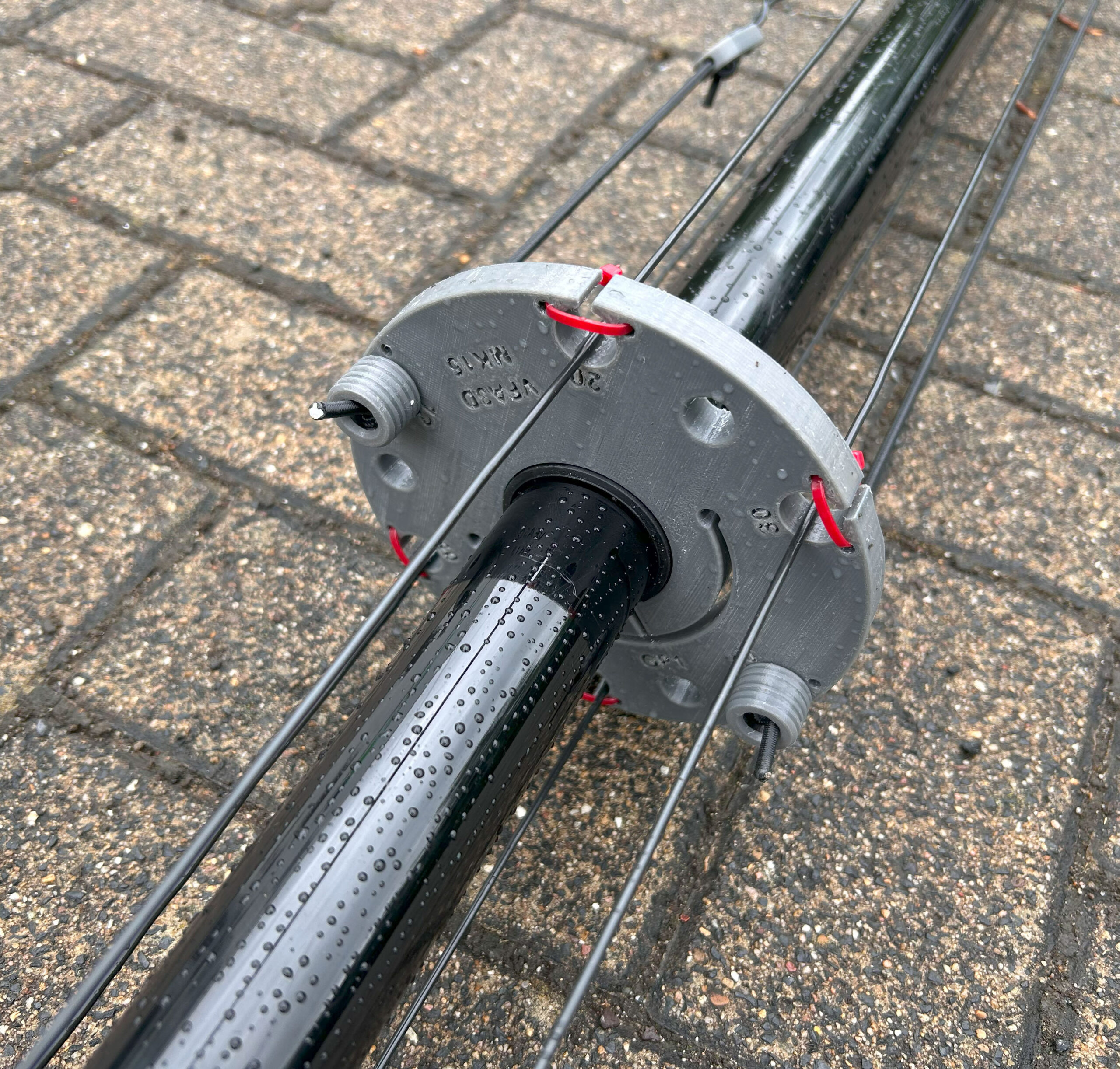
Vertical multi-band antenna – 3d printed clamping rings
The individual elements of the GFA mast are secured with 3D printed clamping rings. The clamping rings always sit on the lower transition. The advantage of using the clamping rings is that the GFA elements only need to be lightly clamped together, which simplifies dismantling. Top view Bottom view The opening for inserting the M5 … Weiterlesen
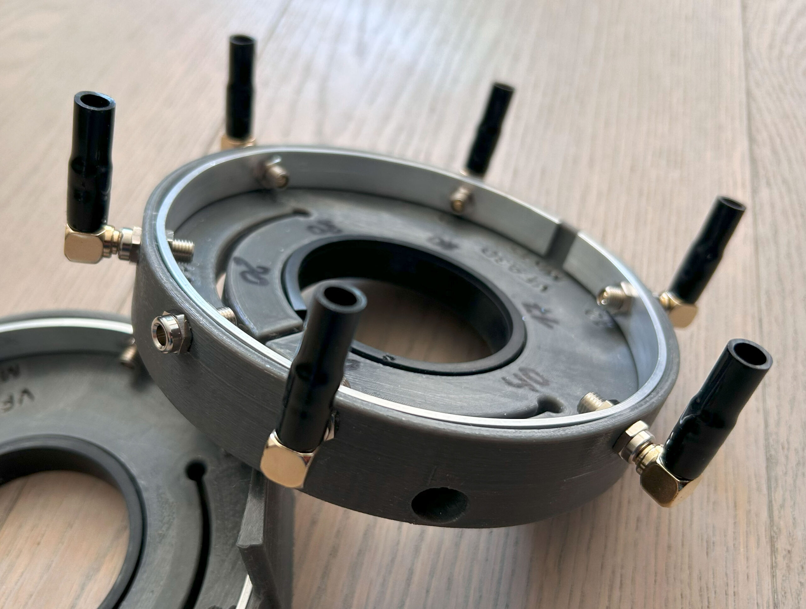
Vertical multi-band antenna – 3d printed radiator plate
The 3D print for holding the radiation elements is printed with PETG filament and has the same basic concept as the base plate. The only difference here is that angled 4 mm banana plugs are used instead of the straight 4 mm banana plugs. The radiant elements of the radiator plate are connected to the … Weiterlesen
Vertical multi-band antenna – 3d printed base plate
Base plate printed from PETG filament equipped with 8 pcs. of 4 mm banana jacks and one SO-239 socket. The radials are connected via 4 mm banana plugs. The use of banana plugs allows for quick assembly. The radial wires and the outer conductor of the SO-239 socket are connected to each other with a … Weiterlesen
Raspberry Pi5 – undervoltage error
Disclaimer Reproduction is at your own risk. I accept no liability for the correctness of the information or damage that may occur. Background information During my project pihlSDR-Enclosure I encountered the problem that my Raspberry Pi5 sporadically switched itself off. After a few attempts and research, I realised that it was an undervoltage problem. I … Weiterlesen